

Engineering-driven durability.
Premium quality. Reliable power. Engine components engineered for sustained load, elevated thermal stress, and repeated high-pressure operation — durability isn't the only goal, it's the starting constraint.
- Experience
- 20 yrs
- Alloys
- 4032 · 2618
- Platforms
- EA888 · EA855
Engineering-driven durability.
Our sourcing standards prioritize structural integrity, repeatability, and long-term stability. Composition control, forging quality, heat-treatment consistency, and machining discipline determine real-world behavior.
Structural integrity
Components engineered for sustained load, elevated thermal stress, and repeated high-pressure operation.
Repeatability
Composition control, forging quality, heat-treatment consistency, and machining discipline — measurable, not marketed.
Nearly two decades
The engineering team behind QUIRA has designed and manufactured internal components for established performance brands and high-output applications.
This experience shaped our understanding of where to exercise caution, where precision is critical, and where controlled innovation delivers measurable improvement.
Failure-mode driven design.
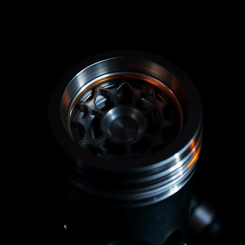
Load path analysis defines geometry. Force distribution across crown, ring lands, pin bosses, beam sections, and bearing interfaces is evaluated under sustained operating conditions.
Failure modes considered
- Ring land fatigue
- Pin boss distortion
- Skirt instability from thermal-growth miscalculation
- Beam deformation
- Bearing fatigue under pressure spikes
Design decisions prioritize fatigue resistance and controlled margin over minimal mass. Our starting lineup fills the gap between one conservative approach and another more daring one — accommodating both objectives across a broad spectrum of conditions.
4032 vs 2618 — alloy strategy.
Alloy designation alone does not define performance. 4032 and 2618 differ in silicon content, thermal expansion, and ductility characteristics.
4032-T6
- Higher silicon content (~11–12%)
- Lower thermal expansion
- Strong dimensional stability
- Balanced and endurance-oriented builds
2618-T61
- Low silicon content (<2%)
- Higher ductility
- Increased tolerance to extreme cylinder pressure
- High-boost and competition-focused applications

Alloy choice must align with intended engine strategy and clearance philosophy.
Combustion strategy, defined.
Compression ratio defines combustion strategy within a turbocharged engine system. Dynamic compression for high-boost scenarios and specific requirements.
10.0:1 — near-STD
- High boost margin
- Broad fuel compatibility
- Conservative ignition flexibility
- Robust forced-induction foundation
12.5:1 — high CR
- Efficiency-forward architecture
- Particularly well suited for ethanol applications
- Enhanced spool characteristics
- Improved off-boost response
Neither compression ratio is inherently superior. Selection should be based on intended fuel strategy, boost targets, turbocharger sizing, and usage.
Crown design manages pressure, not just compression.
Crown geometry manages pressure development rather than simply increasing static compression. Flame-front stability, thermal distribution, and structural integrity are preserved through controlled contour transitions and balanced material distribution.
Adequate static compression combined with engineered crown design can contribute to improved off-boost efficiency, transitional throttle response, and turbine energy during spool.
Clearance engineered, verification required.
Valve-to-piston clearance must account for dynamic valvetrain motion at sustained high RPM.
Relief geometry accommodates
- Exhaust: +1.350 mm additional lift
- Intake: +1.0 mm additional lift
- +1.2 mm oversized valve diameter
Integration
Relief pockets integrate with controlled radii to avoid stress concentration while maintaining crown stiffness and ring-land integrity.
Clearance must always be physically verified during assembly. QUIRA defines engineered margin within piston geometry; final validation remains 100% the responsibility of the engine builder.
Load path preserved, fatigue resisted.
Underside forging geometry and pin-boss reinforcement preserve load-path integrity under peak cylinder pressure.
Underside geometry
Forging profile engineered to distribute load into the pin bosses under peak cylinder pressure.
Ring land & skirt
Ring land spacing and skirt design support dimensional stability across thermal cycles.
Balanced mass
Material distribution balances strength and mass control to maintain fatigue resistance under sustained high-output operation.
Pistons — configurations & SKU architecture.
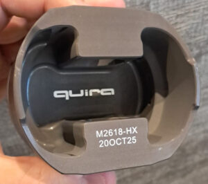
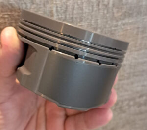
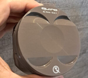
Supported platforms: EA888 Gen 1–3 (1.8T / 2.0T) and EA855 DAZA / DNWA. Available in 82.50 mm (STD) and 83.00 mm (+0.50 mm), both in 4032 and 2618, both in 10.0:1 and 12.5:1.
Compression Architecture
A near-STD static compression baseline with QUIRA structural reinforcement. Intended for turbocharged engines where cylinder pressure is managed through boost and ignition strategy rather than elevated static compression.
- High boost margin
- Broad fuel compatibility
- Conservative ignition flexibility
- Robust forced-induction foundation
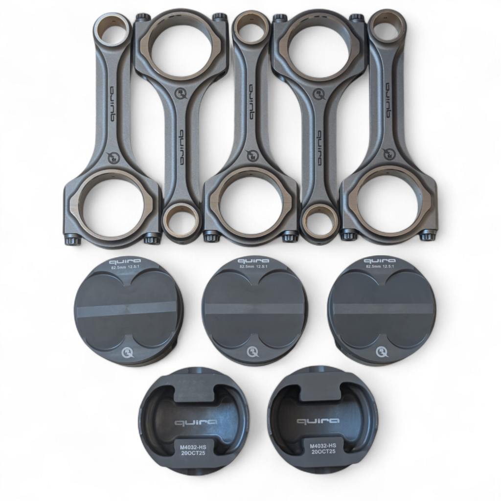
M4032-HS
4032-T6 · standard CR series
M2618-HX
2618-T61 · high-CR series
Structured part coding ensures traceability and controlled specification management.
Lightweight mass. High tensile strength.
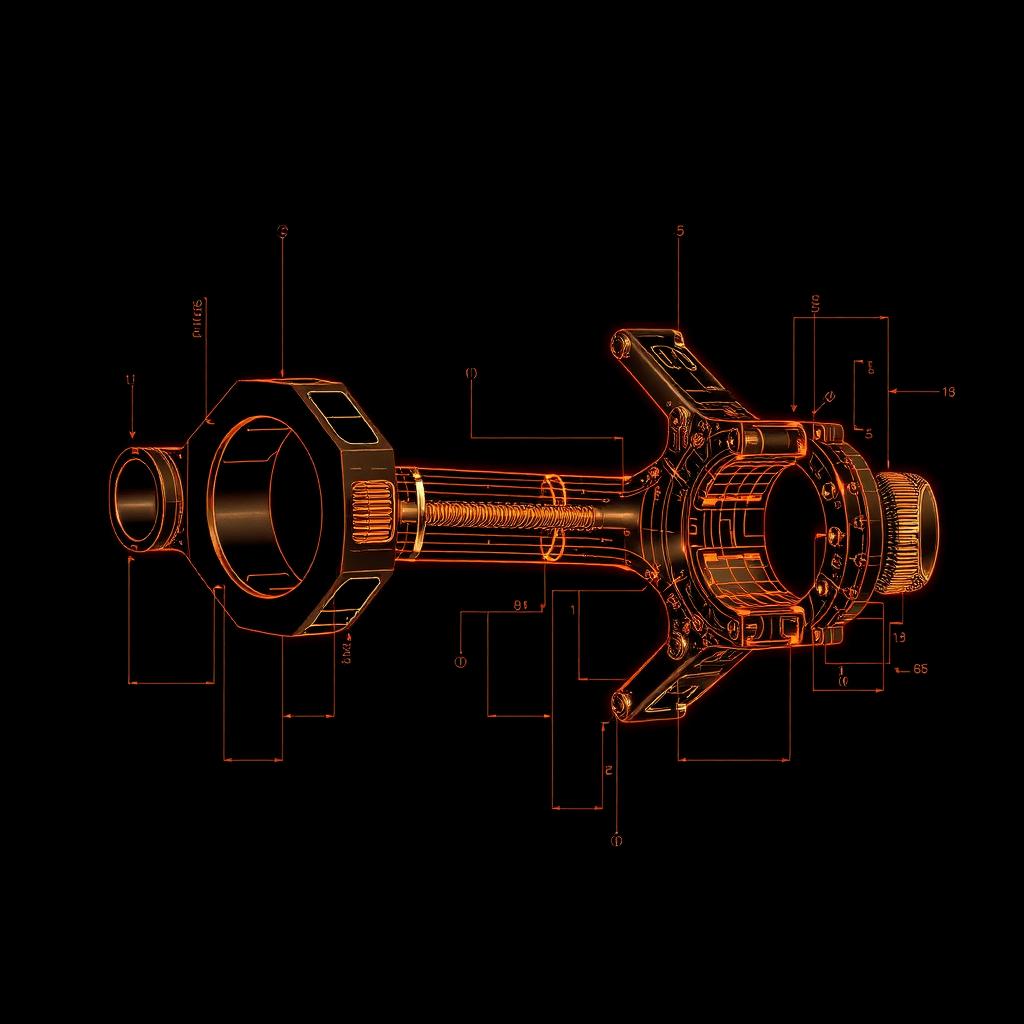
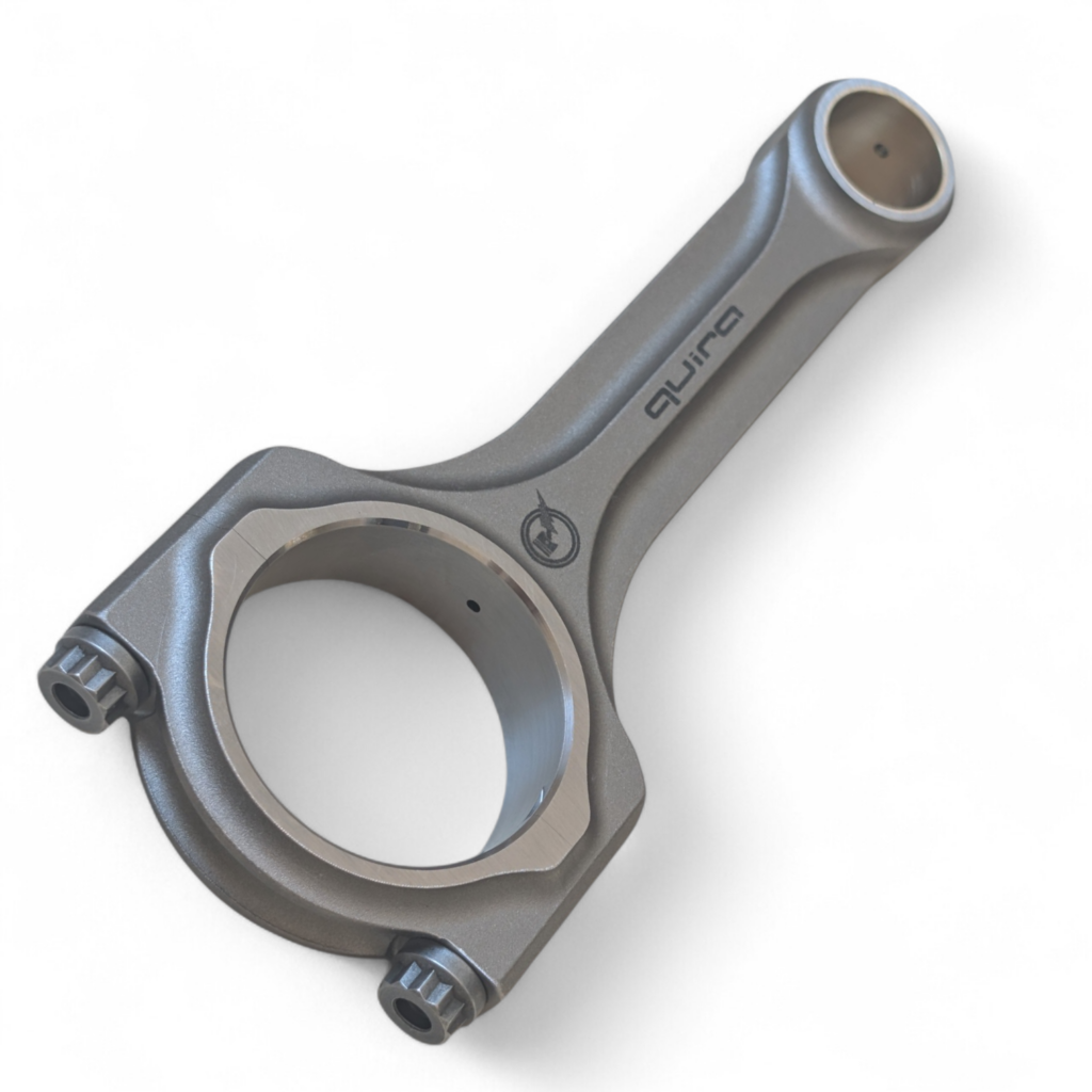
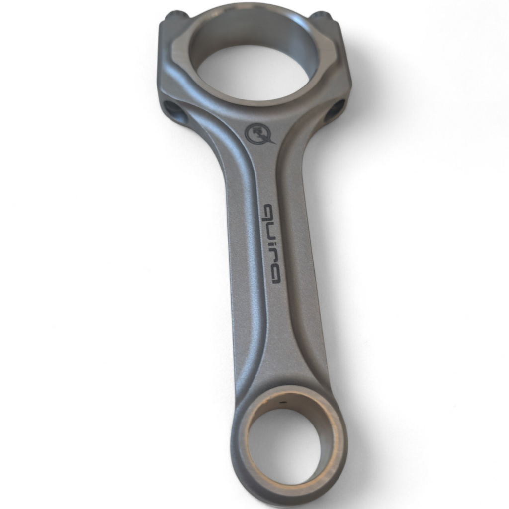
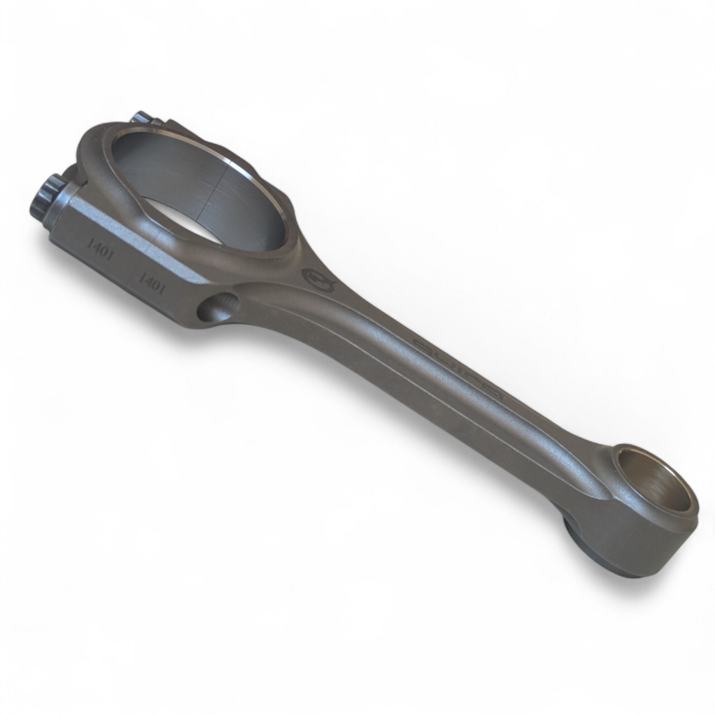
QUIRA Super-Cross rods combine mass optimization with high tensile strength and fatigue resistance. Beam geometry supports stability under sustained high RPM and elevated cylinder pressure.
Architecture
Designed to complement piston mass, load transfer, and long-term durability objectives.
Riffle-drilled centers
Manufactured with riffle-drilled centers to allow lubrication of the wrist pins (correct rod bearings required).
In-house rod bolts
Ship with in-house +220,000 psi tensile strength rod bolts that suffice for very high-RPM setups. Stronger materials are currently under testing for optional future upgrades.
Engineered margin. Verified assembly.
All dimensions, tolerances, and compatibility parameters must be measured and validated during assembly. Final engine performance depends on calibration strategy, fuel quality, component selection, and assembly accuracy.
QUIRA components are engineered to operate within defined mechanical margins when integrated into a properly configured system.
Building something serious?
Reach out for spec sheets, distribution enquiries, or engineering discussion.